More Mega Drive Modding: Towards Bluetooth Controllers#
After the initial work done on the previous post, I decided to try my hand incorporating Bluetooth controller support into the mod. The initial idea seemed straightforward: give the mod full access to the controller IO ports, and sniff or emulate input devices.
We could not only read the inputs being pressed by actual hardware controllers, but ultimately emulate any kind of controller for hardware testing purposes. And if we could connect controllers via Bluetooth, well… We’d have generic wireless controller support on the Mega Drive.
Whatever could go wrong?
The plan#
With this idea in mind, the checklist of what needed to be done was more or less as follows:
Add connections to the IO ports.
The connections need to be bidirectional. We must also be able to set our connection to a HI-Z state. Standard GPIO pins were chosen for this.
Integrate Bluepad32 and add support for controller pairing and event handling.
Considering the pin control code is time-critical, it was decided to handle all bluetooth communication, and serial command processing, on core 0. Core 1 would be responsible for monitoring and controlling the IO pins.
Both cores shall exchange commands using a queue.
To receive signals fast enough, core 1 should use pin interrupts to detect changes of the TH signal, immediately capture the state of the IO pins of that port, and update the internal state machine accordingly.
Do proper level shifting.
This just needed to be done. The first version worked with the 5V signals directly, but the Pico is a 3.3V module. This was not proper, and is unsupported, regardless of it working or not.
That was the initial vision for version 2, more or less.
Design, assembly, and testing#
With the requirements on hand, it was time to sketch out how the connections would look like, and design a proper board for the mod.
IO Port Wiring#
The necessary reset button bypass, and control signals for language and format had already been wired for the first version, So I decided to keep those as they were. Getting at the port signals in an unobtrusive way would require some finessing, though. After checking the clearance, it was decided to solder wires to the bottom side of the board. With some clear tape for insulation, it turned out to be a relatively clean install:
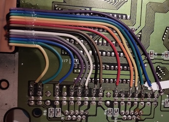
Notice the 1K resistors in series with the connections. I ran the risk of creating voltage dividers when combined with the physical controllers, if more than one pin is not at a high impedance state. This should not happen in normal operation but there’s always the chance of screwing something up, or having a controller be connected unexpectedly. Since I did not want to risk damaging anything, I tried my luck with the resistors.
Level shifting#
For level shifters, I chose to use those cheap preassembled modules that put together level-shifting arrangements based on BSS138 MOSFETs. Something like this.
This was mostly to keep the board easy to solder by hand, and the layout simple, given the amount of level shifting that would be required. It took more board space that would be ideal, but got the job done. (Or did it? More on that later.)
PCB design and assembly#
With a sketch of the connections on hand, it was time to get designing and building. I whipped out KiCad, and in the space of a couple of days I had the design ready to build. So I ordered the PCBs and the components to assemble the board. Only one would suffice at that moment.
With the board assembled and installed, this is what I came up with, hardware-wise:
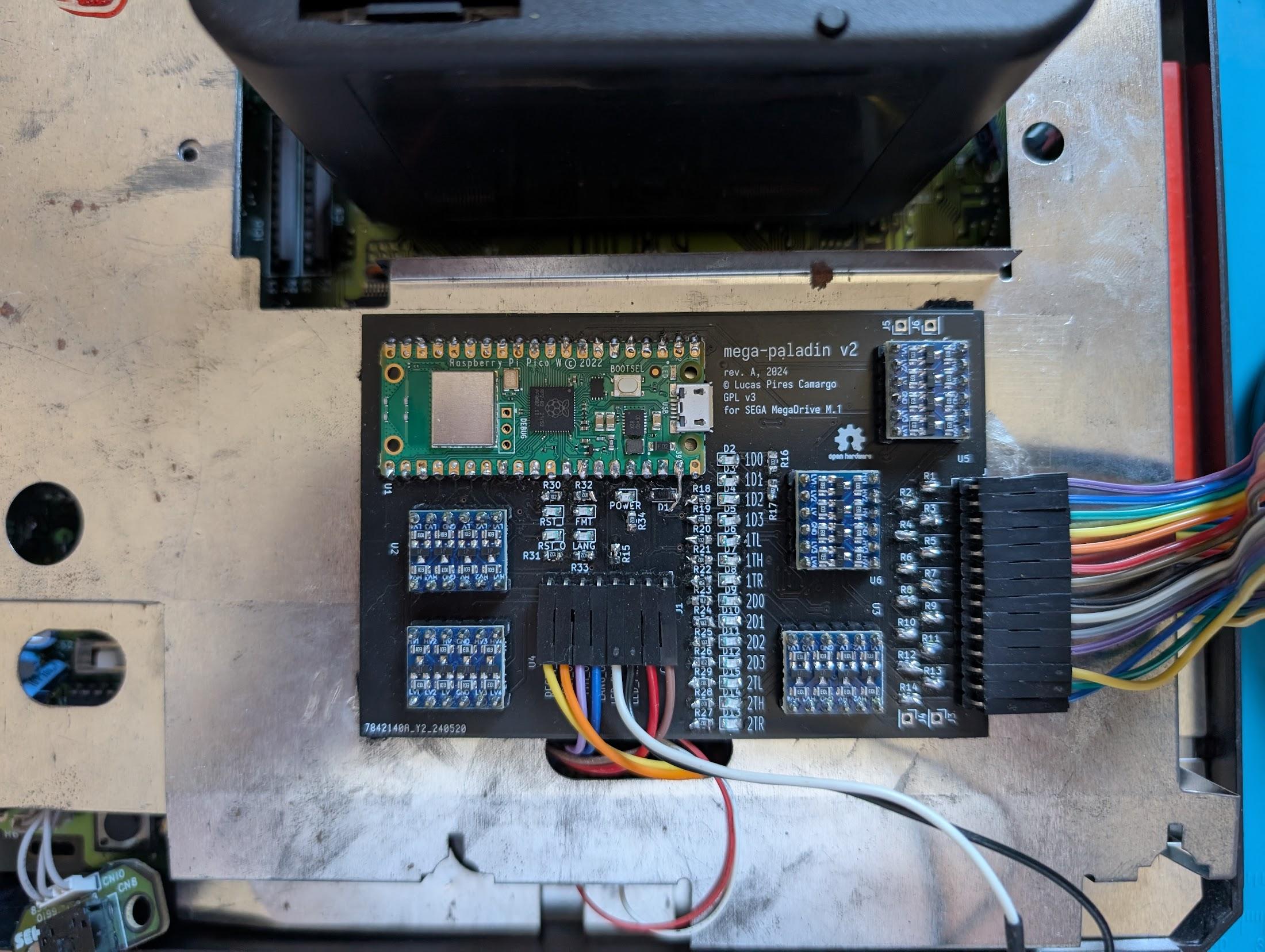
Looks kinda good, kinda janky, doesn’t it? The level-shifting modules were a choice, to say the least. A lot of board space was taken up by that. But al-in-all it was a pretty straightforward board to design and assemble. Why I put the USB port for the Pico in the middle of the board, I really can’t say. I completely overlooked that. Thankfully, a very thin cable took care of connecting to it.
With the hardware in hand, it was time to work on the firmware.
Firmware development and testing#
Bluepad32 inetgration took a bit to stabilize, a this was implemented right after version 3 came out. It had only recently added support for the Pico W. After the stabilization period, the bluetooth stack started working smoothly.
The queue for passing messages back and forth between the cores was also not hard to implement. It just uses the queue utility library from the SDK.
I am not going to go into much detail on the firmware as it is still in flux and not so interesting as of now, as it does not work yet. Spoiler alert.
The real issue was the signal timings. Even when using GPIO interrupts, very ofter controller updates were missed entirely. Sometimes even the oscilloscope would miss the pulses, even with the triggers properly configured.
This was really concerning, and put the whole project in jeopardy.
Where it went wrong#
Turns out that the timing was never going to work. The controller states may change within 0.7 μs. Despite the RP2040 running at 125 MHz, this is too fast for working with GPIO interrupts to bit-bang the port interfacing. Moreover, for signals of this speed, the BSS138 level shifting is just too slow. What an unfortunate situation.
The level-shifting speed aside, one possible attempted solution was to use PIO, but it hit a major roadblock quite soon. To operate on a set of pins, they must be consecutive, if gross workarounds are to be avoided. Some of the pins used on the ports are too ar apart. This would also necessitate two quite different sets of PIO programs, two for each port. Ultimately, the pinout chosen for the Pico was not going to work for PIO.
All fo this could have been avoided if I had sat down and carefully made the calculations for the cycle times from the start, and more carefully chosen the hardware I was going to need. Hindsight really is 20/20.
In any case, it was not looking good. What then?
Necessary improvements#
Considering all the things that did not go well, it became evident that the board needed a revision. Only then it would make sense to continue working on the firmware.
So I came up with the following laundry list for version 3:
Use a decent, proper level-shifting IC to do this job. Something you can actually look at the datasheet and say “yeah, that will be fast enough”.
Have the pins for a port follow a consistent ordering, and be contiguous. This is important for using PIO effectively.
Bonus: do it in a way in which the hardware UARTs can be used with smdt, a very cool terminal emulator for the MD. If a PS/2 or Saturn keyboard could be emulated from a bluetooth keyboard as well, this could be a killer mod for this (impractical) purpose!
And please, for the love of whatever, get the Pico’s USB port on the board’s edge!
My move, again.
Version 3 in progress#
So, before actually implementing the changes, I took a long break from this project. I decided to leave it aside for a bit and do other stuff. In fact, almost a year had passed since the last firmware commits, before version 3 was taken up a few days ago.
After a few hours of free time retooling the design, this is what I came up with:
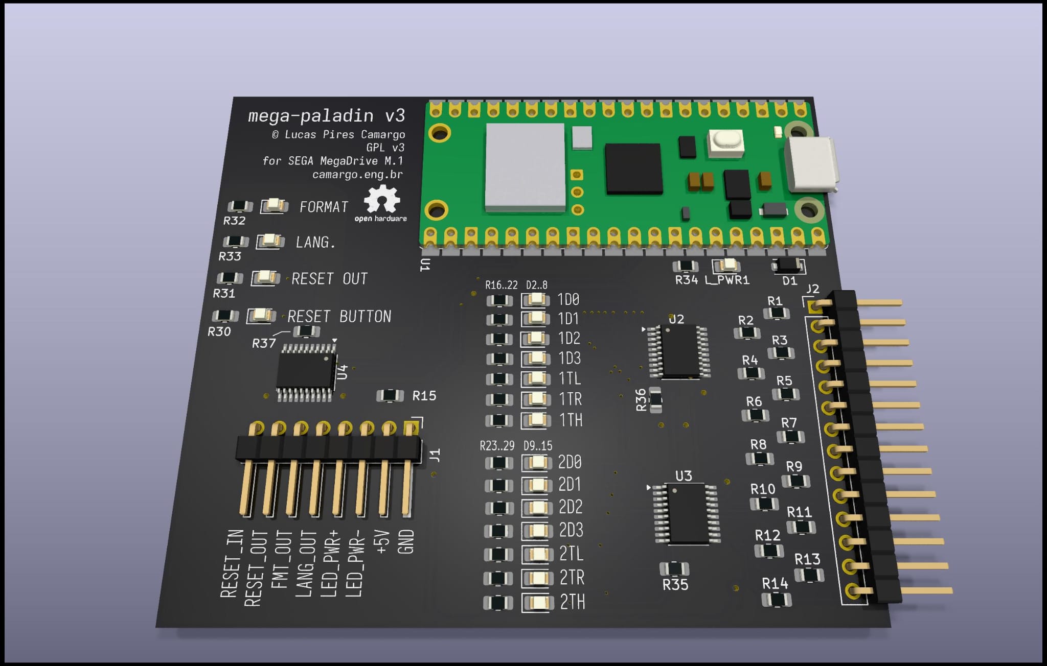
Let’s go over the changes:
Port pins are now contiguous, so the firmware can leverage PIO for interfacing.
…and the TX and RX pins used for smdt (TL and TR) concide with the RX and TX pins of the hardware UARTs. Good serial support would now be possible.
I am using proper, fast level-shifters for the signals this time around. Namely, the TXS0108E. From the info on the datasheet, we should be good.
A nice side-effect is that we now have output-enable signals on the level-shifters, so we can enable or disable the connection to the port via software. By adding a pull-down resistor to the OE signal, we can ensure that the port interfaces don’t interfere with the system, since the MegaDrive side starts at a high-impedance state. The ports can be enabled later via a dedicated GPIO pin.
The new level-shifters are much more compact than those modules, which allowed me to remove more or less an inch of board width.
The height, and more importantly, the relative positioning of the connectors, remains the same. Don’t want to fix what’s not broken.
Connector pinouts also remain the same, so no further wiring changes to the MD are necessary.
Some proper mounting holes were added (not in this render, added right after). If they’ll be used is another story.
USB port in the proper location. Sigh of relief.
All in all, a nice all-round improvement. And this time, I am using an assembly service, to save me the pain of hand-soldering. Only the Pico will need to be added-in.
The board is still relatively sparse, more stuff could be crammed in. There are four unused level-shifting channels, for example. But I really had no reason to make up usecases. The priority is making this functional as-is.
As of yesterday, some prototype boards are already in production. When they arrive, firmware development will continue. Hopefully, on the next post about the project, it should be working well. Regardless, this was a good opportunity to write about the efforts so far, since the project is fresh in my mind again.
All of this development is being mirrored here (GitHub). It will be added to the projects list when a first working version is achieved.
Vamos lá.