Microcontroller and Instrumentation Experiments#
Holidays are still going strong here in Rio. But I guess as a result of some subconscious new year resolutions, it is finally time to clear up the publishing queue a little bit. Blogging has been slow because things have been moving past me alarmingly fast. From the top of my mind, the first thing that comes up is that I presented a paper at SBESC 2015 in Foz do Iguaçú (link to it when the proceedings are out). A huge shout-out to my teacher and mentor Giovani Gracioli is in order: every single meetup or thing we do together is a lesson. Thank you so much.
This post is not about proper research activities though, that is coming up at a later date. Now I’d like to ramble about some experiments done in two courses: Microcontrollers and Instrumentation. Working within the limitations of the Tiva C series Launchpad by TI as an interface board with the PC, my tasks were to interface with varied low-cost sensors, trying to build valid instruments out of the setup, and testing them. Being the Qt junkie that I am, for each of them there is a Qt/QML computer program that provides the interface. Here they are:
Sound Frequency Meter#
 Trying to make sense of noisy input
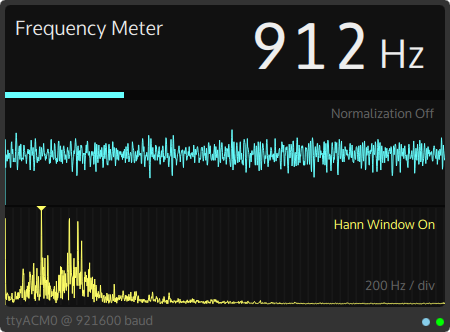
The first project goal was to construct an useful measurement instrument out of a microphone breakout board not unlike this one. It did not have an analog-out though, so some analysis and pin soldering was needed. I decided to go for a frequency meter application because the necessary algorithms (FFTs) are readily available in good quality. The chosen library to do the decoding of the audio data was libfftw.
In the board firmware, a simple program samples the ADC at 22050Hz via a timer. The most significant 8 bits are then sent to the PC via serial. It is a crude mechanism. An improvement would be using the USB device interface for proper sound capture. However the computer application takes care of interpreting the data as audio and analysing it. There are options to normalize the input for display and also turn off the Hann Window used in filtering the input.
All the analyzed data is drawn via QML’s Canvas element and some simple Javascript, both the input waveform and the representation in the frequency domain.
A report (in Portuguese) was written with more details.
Rotation Speed Meter#
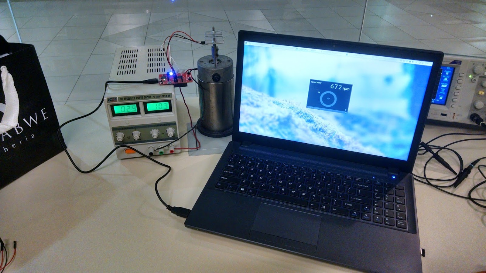 The complete test setup
On a second Instrumentation task, I was given a very simple rotary quadrature encoder, and a brushed permanent-magnet servomotor to go with it. My task was to assemble both together somehow, and use the encoder to measure the current speed of the motor.
The coupling of the motor is something quickly put together in the course of a day in the fabrication lab. The most interesting part of the assembly process was the manual machining of the axle coupling with a lathe.
The capture board was required to do more this time, taking care of debouncing and interpreting the state changes of the input signal. There are hardware peripherals on the Tiva (QEI) specifically for interfacing with such encoders, however they could not be used successfully because the cheap encoder was too noisy for the QEI to handle. So debouncing was implemented in software and the output to the PC was in the form of ‘L’ and ‘R’ character pulses to indicate that the encoder moved. The implementation for this is based off of some Arduino code I found around the web. It was used because I thought the event transition scheme of the event machine was very elegant and (cursorily) performant.
The PC application used the skeleton of the previous one and is much simpler this time, counting pulses in a period of time and estimating rpm accordingly. The report goes as far as this point in development. However, as some sort of project epilogue, An H-Bridge came into play. and some rudimentary speed control for the motor was assembled and implemented. That was the most fun part of it all.
Camera Interfacing#
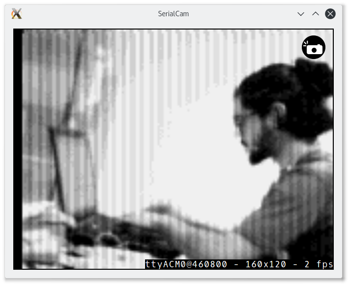 Using friends as models
For the Microcontrollers course, my task was to interface with a VGA camera with a parallel interface (and I²C for control), the OV7670 module. The module does not have a framebuffer and the transfer data rate is too much for the serial interface. Since I was trying to avoid all the hassle of the USB interface because I didn’t have much time, I decided to try and see what could be done without it and without DMA to keep things simple. Turns out it was possible to fit a 8bpp QQVGA picture in the device’s RAM as a framebuffer. With it, it was not necessary for the serial data rate to be very fast (and unreliable). Capturing would then be done in a scan-transmit serial fashion.
The PC viewfinder used the same serial access class wrapped in a camera interface, but a whole different UI code, using QGraphicsView, which was deemed easier for this application. A button can be pressed to save the image too.
Around 1.7 fps were achieved using this scheme. Can we do better with the Tiva? Using USB and DMA, I believe so. But is the Tiva’s main processor fast enough to stream a full VGA frame, in color, and at 30fps? I wouldn’t bet on it. Hardware engineers are probably cringing right about now thinking of this setup. This is the kind of development task an FPGA is expected to excel at. Then again, just that it ultimately works is in itself an interesting thing.
Source Code#
The source code for these experiments is in this repository. Hopefully It can help someone that needs to hack something quickly together using Qt and the serial port to interface with custom hardware.
That’s for today. Happy New Year!!! 😀