Hydrus Project Update#
(This should have been published months ago but I was so busy with the project itself I kinda forgot it was aon the drafts)
A lot has been happening in the Hydrus Project front. The deadlines are getting tighter and there is still a ton of stuff to do, for the whole team. In this post I’ll go through what is new, what was accomplished, and the what main challenges were for getting there. Finally, I’ll summarize what is left to be done and ponder over any loose ends.
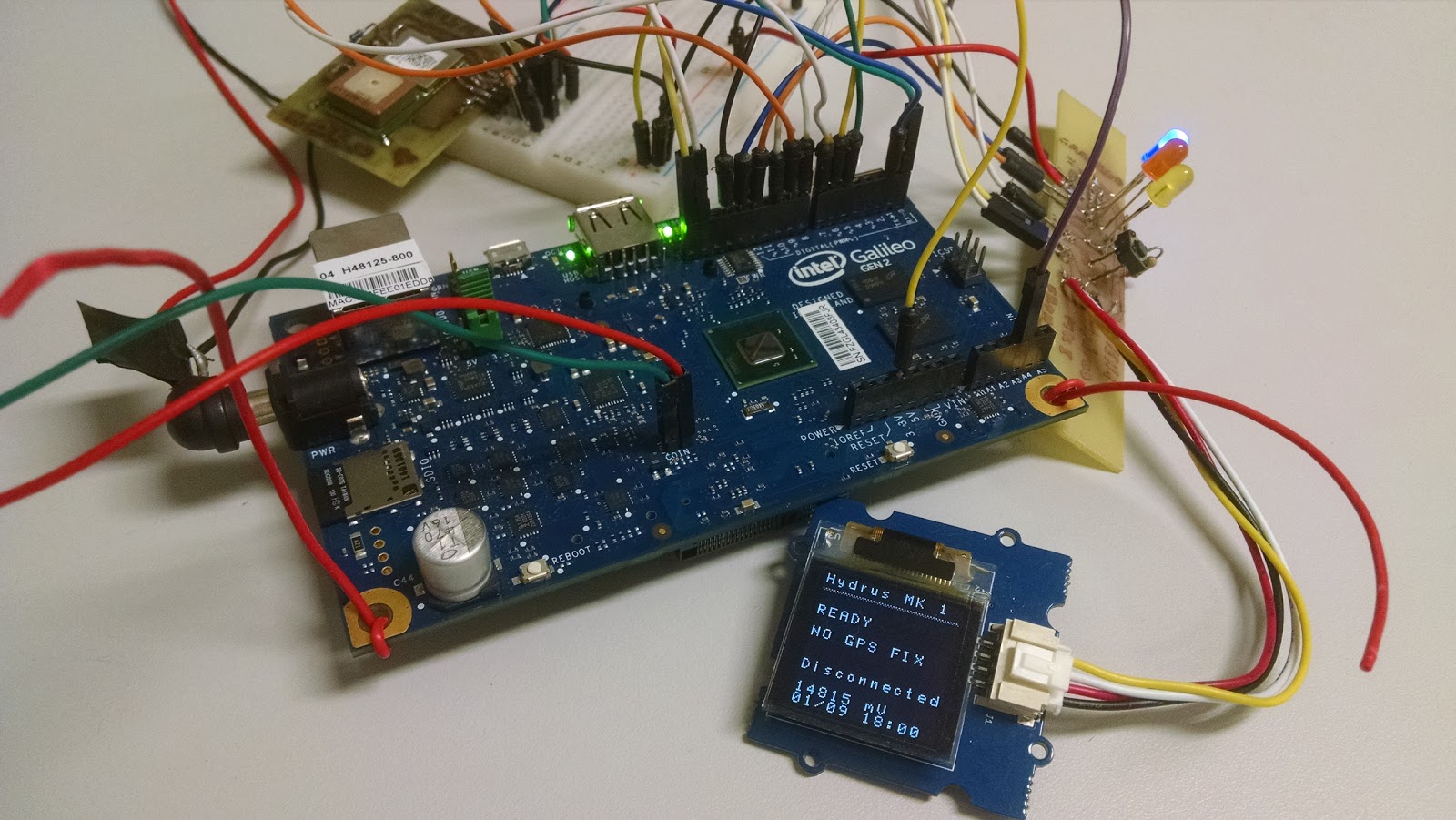 Some of the boat’s electronics, as assembled in our test bench
System Board#
In an effort to consolidate the electrical and electronic project of the boat, a new system board is being finalized. It has more of an integration role, presenting a ton of connectors for the different sensors and subsystem modules. It also contains an instrumentation amplifier for the PH probe, and a slave Arduino Nano for dealing with the ultrasonic sensor array. The Nano can also be used for interfacing with other less important sensors, or other platform features, should the need arise.
The whole project is being done in KiCad, an open-source EDA suite. A custom component footprint for the GPS module had to be drawn, but all in all, most needed stuff was already in place. I really enjoy working with KiCad. It is simple, yet featureful, rarely getting in my way. And the 3D preview is a very nice bonus.
The hardest part of the layout process was my insistence in using only a single copper side. This is very important for me since we do not have a PCB prototyping machine, so the production techniques at our disposal are rudimentary. At best. But after a lot of swapping components around and painstakingly tracing everything by hand, it was possible to arrive at a viable layout, with only a single jumper resistor.
Construction
of the board is expected to begin shortly, using PCB homebrewing
techniques. If only we could make it look as good as in the 3D preview,
with solder masks and silk layers and all… boy I’d be really happy.
Boat Frame#
The plug for the hull mold is being fabricated out of a styrofoam model given to us by one of our Joinville colleagues, that just graduated as a naval engineer. Everything is being done in the models lab, LabMod. The styrofoam model was covered in plaster and sanded to a smooth finish, converting it into a solid plug. It was then used to laminate a female fiberglass mold. We are now in the process of using the mold to derive both of our hulls.
Êmili is making sure our hull comes out nice and strong. The team expects the final boat frame to look pretty good, not bad at all for a bunch of mechatronics nerds. We are still figuring out the best configuration for the middle platform, and should be able to integrate the electromechanicals and electronics into the frame in a matter of weeks.
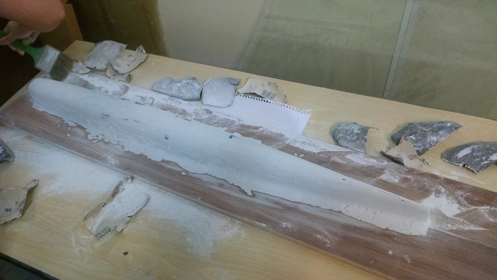 The hull plug during sanding…
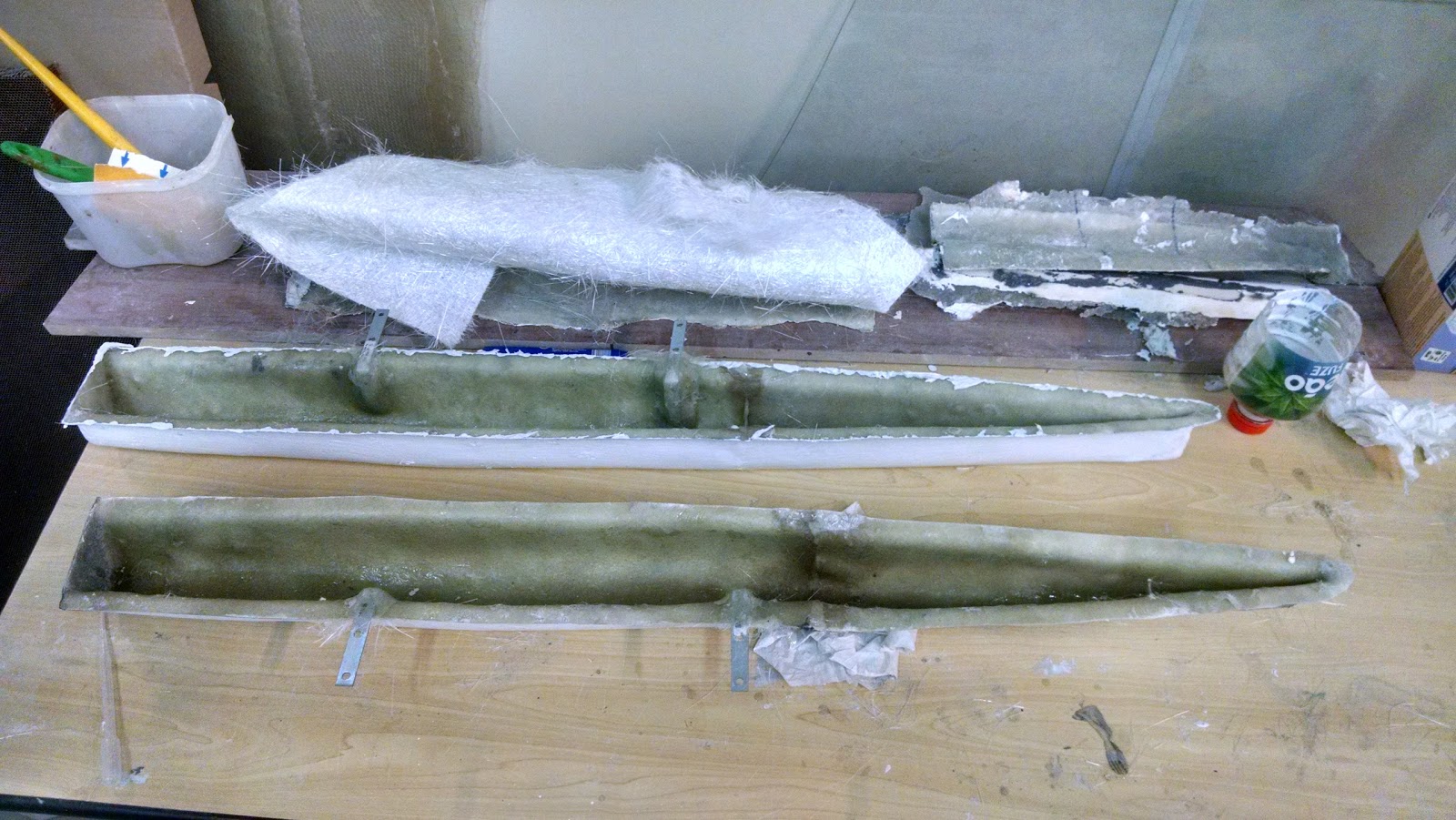 ..and the hulls after being laminated inside the negative
Software#
The station desktop program can now edit navigation routes and has received general polish. It did not change much though. The meatier part is the new simulation mode. I’ll talk about it shortly.
Most changes went into the drone firmware, as it acquired more capabilities and is now approaching a water-ready state. The original software architecture did not change at all, since it has proven to be a viable base for implementing all the required features for the prototype.
One step back is that it was not possible to use a separate thread for driving the I2C bus, and by extension, the OLED screen. This is unfortunate as the screen update rate was already qslow. Now it has to be driven opportunistically, during slack time in the main thread. This will be investigated further, if time allows. It is not an essential feature of the project, but if the need for removing the screen ever comes, its bling factor will surely be missed.
Control and Simulation#
Nothing of the above would amount to much if the boat could not fulfill it’s main purpose: autonomous navigation! Alright, we’d still have a cool boat. Anyway, we want a control loop running in the firmware.
I decided to implement it as a sort of state-machine control loop multiplexer thing. For every state, there is a basic behavior, that in a certain condition might advance the simulation towards the next logical step. This made control much simpler to implement, in place of having a monolithic, very complex controller.
There is also a simulation mode embedded into the station application, which can override some sensors and actuators according to a simplistic model, for testing.
Next Steps#
This project is big. Like, huge. A lot of stuff. I had no idea what I was trowing myself into. But yeah, that’s life. We’ll manage. Huge thanks to my teammates for putting up with everything and remaining calm, collected and motivated.
The time for presenting everything is approaching fast. Let’s see how this will turn out. Until next time!